
- DFM first, cutting second — every drawing gets a manufacturability review before a quote, and the flags are free.
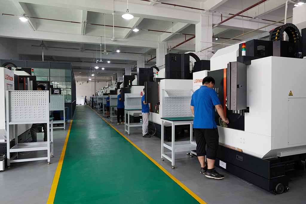
- 100+ production machines — 3-axis (50+), 4-axis (20+), 5-axis (20+), 25+ lathes, 7+ grinders in a 6,800 m² facility. ±0.003 mm milling / ±0.002 mm turning, ±0.002 mm grinding, verified on Hexagon CMMs.
- MOQ 1 piece; lead times ~3 / 7 / 30 days by complexity.
Why does manufacturability matter more than unit price?
Two shops can quote the same drawing and produce parts that look identical, yet one runs quietly for years and the other churns out scrap. The difference is usually not the machines; it is whether the design was made manufacturable before cutting. A part with sharp internal corners, a wall too thin to clamp, or a tolerance held tighter than function needs will cost more and yield worse no matter who runs it. Fixing those things on the drawing is the single biggest cost lever in machining, and it costs nothing before the order.
This is why the DFM review is the first step here, not an afterthought. You send a drawing; you get back specific, actionable flags with reasons, not a vague promise to "make it work."
Which drawing features most often make a part expensive?
A handful of geometry decisions account for most of the avoidable cost in machined parts. Each one is cheap to fix on the drawing and expensive to live with in metal.
| Feature | What makes it expensive | The cheap fix |
|---|---|---|
| Sharp internal corners | A round cutter cannot make a square inside corner; it needs EDM or hand work, or a long reach | Add a radius at least half the cutter diameter |
| Deep, narrow pockets | Long-reach tools deflect and chatter, forcing slow feeds and more scrap | Make the pocket shallower or add draft |
| Thin walls | They flex under clamping and cutting, then spring back out of tolerance | Thicken the wall or add support ribs |
| Over-tight tolerances | Every tightened band slows feed and adds inspection on a feature that may not need it | Tighten only the dimensions that control function |
| Deep threads near a shoulder | A standard tap cannot reach the bottom; a thread relief is needed | Add a thread relief or specify a shallower thread |
The pattern is the same in every row: the drawing asks for something the process delivers only at a premium. A good DFM review finds these before they become your problem.
How do you specify tolerances without paying for precision you don't need?
Tolerance is priced on a curve, and the curve bends sharply upward. Going from ±0.1 mm to ±0.02 mm is nearly free — any modern machine holds it. Going to ±0.003 mm (milling) / ±0.002 mm (turning) costs real money, because now tooling, inspection, and feed rates all tighten. Below that, grinding enters at ±0.002 mm as a second, finer process.
| Tolerance band | What it demands | Relative cost |
|---|---|---|
| ±0.1 mm | Standard machining, fast, no special handling | Low |
| ±0.02 mm | Standard CNC with routine inspection | Moderate |
| ±0.003 mm (milling) / ±0.002 mm (turning) | Tight process control, CMM verification, slower feeds | High |
| ±0.002 mm | Grinding as a finishing pass, plus CMM and roundness checks | Highest |
The DFM review flags exactly which dimensions on your print are over-specified, so you pay for precision only where it earns its keep. On a representative length characteristic (76.1–76.5 mm), our SPC record shows Cpk = 1.851 (one characteristic on one part, not a blanket capability claim) against an initial-study target of Ppk ≥ 1.67.
One more check on that number: the 0.4 mm band behind it is wide by design. Hold the same process spread against a ±0.005 mm feature and it fails outright, so read this figure as evidence about one characteristic on one run, not as a blanket tolerance claim.
How does the 4th axis improve manufacturability?

Every time a part is re-fixtured, it picks up a small positional error and an extra setup charge. A 4-axis machine can index the part and machine multiple faces in one clamping, which does two things for manufacturability: it removes the re-fixturing error that accumulates across flips, and it lets features that reference each other across faces be held in true position to one another. A part with features on four or more faces, or with cross-holes and side slots, is often more manufacturable on a 4-axis setup than it is as a five-flip 3-axis job.
How does material choice change manufacturability?
Material is not neutral on cost or on how reliably a part machines. Aluminum cuts fast and anodizes well, which makes it the default for prototypes. Stainless and alloy steel cut slower and wear tools faster. Titanium holds shape well but cuts slowly and builds heat that must be managed, and its stress-relief needs a higher temperature than our in-house ovens reach, so it goes to a qualified partner.
| Material family | Grades run | Buyer note |
|---|---|---|
| Aluminum | 6061, 6063, 6082, 7075, 2014 | Fast, affordable, anodizes well — default prototype choice |
| Stainless steel | 303, 304, 316, 316L, 17-4PH | 303 free-machining; 316L for corrosion; 17-4PH for strength |
| Carbon / alloy steel | 1018, 1045, 4140, 4340, 12L14 | Carburizing or nitriding available for wear parts |
| Brass / copper | C360, H62, C110 | For electrical and thermal conductivity |
| Titanium | TA2, TC4 (Grade 2 / 5) | Stress-relief above 500 °C outsourced to a qualified partner |
| Plastics | ABS, POM, nylon, PTFE, PEEK | For non-metal prototypes and insulators |
Every incoming lot is checked by XRF against its mill certificate before it reaches a machine, so the alloy you specify is the alloy you receive — a substituted or mixed lot is caught at the door, not discovered on your dock.
What are the geometry red flags you should know?
Whether you buy from this shop or any other, these are the design calls that separate a makeable part from a problem. Ask any supplier — including this one — how they handle each.
- Internal sharp corners — ask for the minimum radius, or expect a premium.
- Deep holes with tight tolerances — a hole ten diameters deep is a drill-deflection risk, not a routine feature.
- Unsupported thin sections — they flex, then spring back out of tolerance.
- Surface finish on every face — finishing only the faces that matter is where the savings live.
- No datums on the drawing — a drawing without datums leaves the shop guessing which face to measure from.
Send a drawing and we will run these checks on it for you, in writing, before you commit.
How are parts verified after the DFM review?
A manufacturable design still needs proof it was made right. Critical dimensions are checked on Hexagon GLOBAL S CMMs, with surface finish and profile measured on a KEYENCE VK-X3000 laser microscope and a SURFCOM 1800D. Hardness, coating thickness, salt spray, and tensile are all covered in-house, and SPC control charts run on key characteristics — Ppk ≥ 1.67 initial critical, ≥ 1.33 general. The DFM review prevents the problem; the inspection bench proves it stayed away.
What are the MOQ and lead times?
There is no production minimum — the MOQ is 1 piece, so you can machine one part, measure it, and iterate before committing to volume. Lead time is set by complexity and the number of process steps, not by a blanket promise.
| Complexity | Approx. lead time | Typical profile |
|---|---|---|
| Simple | ~3 days | Few operations, single material, no finishing |
| Standard | ~7 days | Multiple operations, standard tolerances |
| Complex | ~30 days | 10–20 process steps, or surface finishing / heat treatment |
What should a drawing include before you ask for a quote?

The fastest quote is one that answers every question up front. A complete request is a file plus the decisions that change the price.
- The model or drawing: STEP or IGES for 3D, or a 2D drawing with every dimension and tolerance.
- Material and grade: name the alloy, not just "aluminum" or "steel," plus any heat treatment or plating.
- Quantity: prototypes and production runs quote differently.
- Critical tolerances: mark which dimensions control function; leave cosmetic surfaces loose.
- Target date: state when you need it, and we will tell you honestly whether it holds.
How do datums and true position shape the 4-axis decision?
A drawing with datums is a drawing that tells the shop what to measure from; a drawing without them leaves the shop guessing which face is the reference. On a multi-face part, the datum callouts are exactly what decide whether the 4th axis is worth it.
When a true-position callout spans two faces — say a bore on one face that must be positioned relative to a datum on the opposite face — the part belongs on 4-axis, because the datum never moves between faces. The same callout on 3-axis is only as good as the re-clamping discipline, and every flip adds error. Read the datum scheme first: if the datums live on different faces, the geometry is already telling you it wants to be machined in one clamping.
The same logic applies to profile and concentricity callouts. A datum that wraps a round body is an indexing cue; a datum on a single face is a 3-axis cue. The drawing language is the routing decision, written down before any chip is cut.
How does material choice affect finishing and protection?
Material decides not just how a part cuts, but how it is finished and protected afterward. Routing the finish wrong is as costly as routing the cut wrong.
| Material family | Common finishing and protection |
|---|---|
| Aluminum | Anodizing (standard or hard), chromate conversion, or powder coat for corrosion and wear |
| Stainless steel | Passivation for corrosion, electropolish for finish, or PVD/nitriding for surface hardness |
| Carbon / alloy steel | Zinc or nickel plating, black oxide, carburizing, or nitriding for wear parts |
| Brass / copper | Nickel or silver plating for conductivity and tarnish resistance |
| Titanium | Anodizing for identification and surface hardness, or passivation |
| Plastics | Usually none beyond deburring; some benefit from a light polish |
The point for DFM is to decide the finish on the drawing, not after machining. A part designed to be anodized needs a slightly different surface allowance than one left bare, and a part that will be plated must hold a looser pre-plate tolerance so the coating lands inside the final band. Naming the finish up front is what keeps a quoting round honest.
How do you move from prototype to production without losing what you validated?
A prototype that works is only half the job; the other half is making sure the production part is the same part. The transition lives in the documentation and the machine, not in hope.
- Validate on production machines. A prototype cut on the same 4-axis centers that will run the volume part carries its tolerances forward; a prototype cut on a special setup does not.
- Freeze the drawing and the process. The validated print, the routing, and the fixture all get locked, so the thousandth part follows the same path as the first.
- Carry the SPC forward. Control charts on the key characteristics prove the process stays capable as volume scales, rather than drifting as the run lengthens.
- Keep the MOQ at 1. With no production minimum, you can re-cut a single part against a changed drawing and re-validate before committing to a run.
The DFM review runs the same way at both ends: free before the order, and the flags it produces are the same flags that keep the production run from rediscovering a problem the prototype already solved.
What this shop actually runs
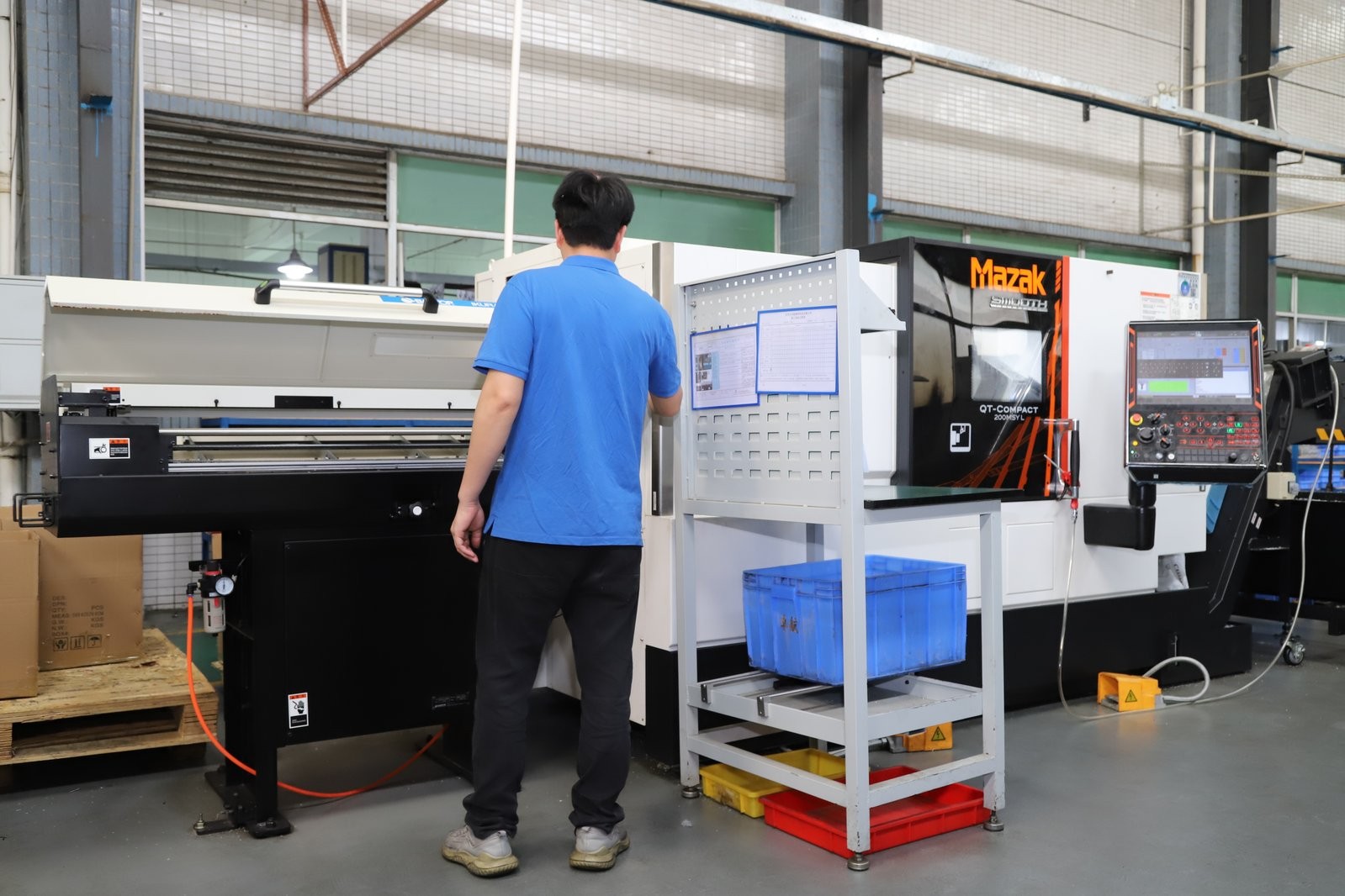
We machine every part in our own 6,800 m² plant in Dongguan, China, on 100+ CNC machines with 100+ staff. The machine list by category:
- 5-axis machining centres (10+) - Mazak VARIAXIS I-600 (510/910/510 mm travel, 12,000 rpm, 22 kW, 71.6 N·m, 30-tool BT40) and Mazak INTEGREX I-250H S (B-axis 0.0001°, 24 kW, 124 N·m, 38-tool HSK-A63). Cut on compound-angle parts, single-setup multi-face prismatic work, and aerospace fittings where datum transfer loss is unacceptable.
- 3-axis / 4-axis machining centres (50+) - Brother SPEEDIO S500Z2N / S700Z2N (10,000 rpm, 14/21-tool ATC, 0.7 s tool-to-tool, Z-axis 2.2 G) and Mazak VCE-430A L / VCE-570C L (10,000 rpm, 118 N·m, 24-tool ATC). Cut on prismatic parts, plates, brackets, housings.
- Swiss-type turning centres (10+) - Citizen Cincom A20-3F7 (Φ20 mm, 10,000 rpm), TSUGAMI B0206-III / B0205-III (Φ20 mm, 0.1 µm), STAR SR-32JII / SR-32J Type N (Φ32 mm, 8,000 rpm). Cut on long, slender rotational parts at ±0.002 mm.
- CNC turning centres (20+) - HEADMAN T70M/1250 (720 mm swing, 117 mm bore, 3,000 rpm, BMT75 12-station turret). Cut on shafts, bushings, flanges up to ±0.002 mm.
- Wire EDM (5+) - Sodick AQ535L (550/350/300 mm travel, ±20° taper, 800 kg workpiece). Cut on hardened tool steel, internal splines, sharp internal corners that milling cannot reach.
- Inspection: Hexagon CMM + 20+ gauges - Hexagon CMM for coordinate measurement, plus vision system, profilometer, hardness tester, coating thickness gauge, XRF for material verification. The 10:1 rule (gauge 10x more accurate than the band) is applied to every feature.
- Machine highlights - VARIAXIS I-600: one-setup multi-face 5-axis + MAZA-CHECK auto-calibration; INTEGREX I-250H S: DONE-IN-ONE mill-turn, B-axis 0.0001° + Ai thermal shield; SPEEDIO S500Z2N / S700Z2N: Z-axis 2.2 G + 0.7 s ATC; Swiss-type: guide-bush switchable + 0.1 µm resolution.
Tolerance: ±0.003 mm CNC milling / ±0.002 mm CNC turning / ±0.002 mm grinding and wire EDM. Capability: Ppk >= 1.67 initial on key characteristics, Cpk >= 1.33 ongoing.
Certificates: ISO 9001:2015 (116024/A/0001/UK/En), IATF 16949:2016 (131941/A/0001/SM/En, with design clause 8.3 excluded, stated openly) and ISO 14001:2015 (116024/B/0001/UK/En), issued to Dongguan Zhuohang Ltd, registration 91441900MA4UWT6X39, founded 2005.
Where we ship: Austria, Belgium, the Czech Republic, Denmark, France, Germany, Greece, Hungary, Ireland, Italy, the Netherlands, Spain, Sweden and the United Kingdom in Europe; Brazil, Canada, Mexico and the United States in the Americas; China, Israel, Japan, Singapore and Sri Lanka in Asia; Australia and New Zealand in Oceania; and South Africa in Africa — plus other countries and regions worldwide, shipped from our base in Dongguan, China.
Contact: Felipe Iglesias, [email protected], +86 13126536955.
Send your drawing for a free DFM review and quote.
Email [email protected] or call +86 13126536955.
Frequently Asked Questions
What is design for manufacturability (DFM)?
In short, DFM is the practice of designing a part so its geometry, tolerances, and material are straightforward to machine. A drawing that ignores DFM costs more and yields worse, because features like sharp internal corners or over-thin walls force extra setups, slower feeds, and more scrap.
What tolerances can you hold?
±0.003 mm on CNC milling, ±0.002 mm on CNC turning, and ±0.002 mm for precision grinding. Critical dimensions are verified on Hexagon CMMs, with process capability Ppk ≥ 1.67 at the initial study on key characteristics and ≥ 1.33 on general characteristics.
Is the DFM review free?
Yes. The DFM review is free before the order and expensive after it. Send the drawing and we return specific flags — a corner radius to open, a wall to thicken, a tolerance to loosen — with reasons, before you commit.
What is the minimum order quantity?
The MOQ is 1 piece. Prototype, single-part, and production orders run on the same machines and to the same tolerances, so what you validate on one part is what you receive in volume.
Which materials do you machine?
Aluminum, stainless steel, carbon and alloy steel, brass, copper, titanium alloy, and engineering plastics. Incoming lots are XRF-checked against the mill certificate before machining, so the grade you specify is the grade you receive.
What are the lead times?
Roughly 3, 7, or 30 days depending on part complexity and the number of process steps. Simple parts ship in about 3 days; parts with many operations or surface finishing land in the 30-day tier.
Are you certified?
Yes — ISO 9001:2015 (116024/A/0001/UK/En), IATF 16949:2016 (131941/A/0001/SM/En), and ISO 14001:2015 (116024/B/0001/UK/En), each with a number you can check with the registrar. The IATF scope excludes product design under Clause 8.3.
How do I get a quote?
Email a STEP or IGES model plus a 2D drawing, material, and quantity to [email protected]. You get a DFM review and a quote, usually within one business day.
Continue reading: 4 Axis CNC Machining Manufacturer · 3 Axis CNC Machining
Standards referenced on this page
- ASTM B211/B211M-19 — Standard Specification for Aluminum-Alloy Rolled or Cold Finished Bar, Rod, and Wire
- ASTM A276/A276M-17 — Standard Specification for Stainless Steel Bars and Shapes
- ISO 9001 — Quality management systems — Requirements