
4-Axis CNC Machining: What Tolerances and Surface Finishes Can You Hold?
4-Axis CNC Machining: What Tolerances and Surface Finishes Can You Hold? — Adding a fourth axis to a machining center lets a part be machined on several faces without re-fixturing, which removes. Tolerances: ±0.003 mm milling, ±0.002 mm turning — ISO 9001 / IATF 16949 verified.
Adding a fourth axis to a machining center lets a part be machined on several faces without re-fixturing, which removes a whole family of setup errors, but it introduces a new axis of truth that the drawing must acknowledge. The rotary axis carries its own accuracy, the features machined in different orientations carry positional relationships across the rotation, and the finishes follow the toolpath as it works around the part.
What does a fourth axis change about how you think about tolerance?
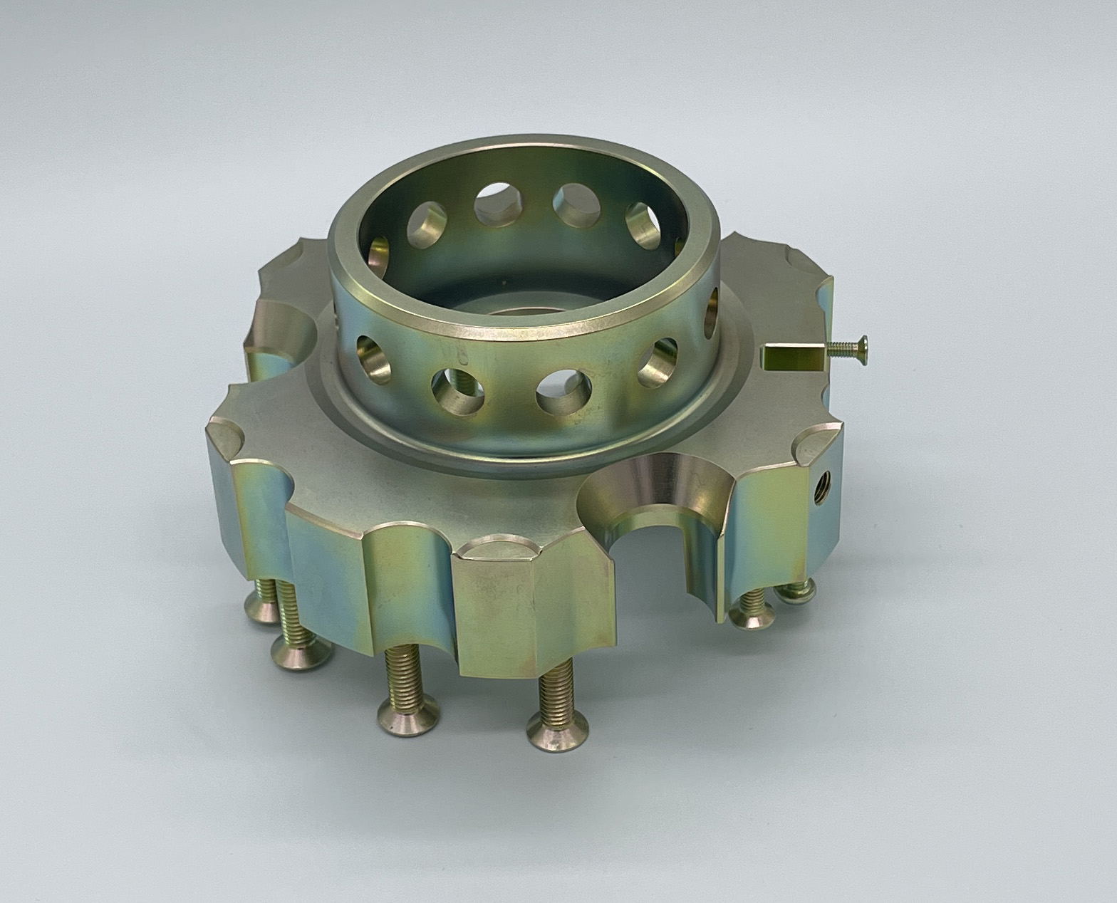
A 3-axis part is machined from one direction, which keeps all the toolpath geometry in one coordinate frame. A 4-axis part is machined from several directions by rotating the part, and every feature machined after a rotation carries the accuracy of that rotation into its position. The tolerance story therefore gains a term that 3-axis work never had: the positional truth of the rotary axis, and the relationship between features cut before and after the part turned. The drawing that acknowledges this term — that calls out the relationship between features on different faces against a defined axis — is a drawing the 4-axis process can be held to.
The fourth axis also changes the setup economy, which changes the practical tolerance available. A part that would need three fixtures and three setups on a 3-axis machine is machined in one or two on a 4-axis machine, and every removed setup removes a chance for the part to be re-fixtured out of position. The same position tolerance that a 3-axis floor would fight across re-fixtures is often easier to hold on a 4-axis floor, because the part never leaves the machine. The tolerance on a 4-axis part is therefore not looser by necessity; done well, it is tighter by construction, and if you understand this, you read the quotation accordingly.
Which tolerance bands apply to 4-axis machined features?
The size and finish bands on a 4-axis part are the industry's standard bands, because the cutting is still milling and turning. On controlled features, milling and turning hold ±0.003 mm (milling) / ±0.002 mm (turning), and precision grinding reaches ±0.002 mm on the features that must run true. The 4-axis addition is the positional accuracy of features across rotations: a pocket machined at zero degrees and a hole pattern machined at ninety degrees carry a positional relationship that depends on the rotary axis and the datum logic, not just on the cutting. That positional relationship deserves its own careful callouts against the axis the rotation happens around.
The rotary axis's own accuracy is a machine property that the buyer rarely sees but should ask about. A rotary table repeats its index position within the machine's specification, and the repeatability of the rotation lands in every feature machined after it. Ask the supplier how the 4-axis work is validated — whether the features across rotations are measured on the CMM against the drawing datums, and whether the rotary positioning is part of the machine's calibration. A supplier that can report the measured truth of features across rotations is a supplier whose 4-axis process is controlled; one that treats the rotary axis as automatically true is trusting a machine it has not checked.
How should datum logic be designed for parts that machine around an axis?
Datum logic is the heart of a 4-axis drawing, because features on different faces must be related through a common reference. The natural datum for a rotated part is the axis the part rotates around — usually the axis of the feature that was centered in the rotary chuck, which is often a bore or a spigot that also locates the part in its assembly. Calling out the cross-face features relative to that axis makes the drawing executable on the 4-axis machine and measurable on the CMM. A drawing that references one face's features to datums on that face and another face's features to different datums has broken the part into unrelated pieces.
The datum logic should also survive the move from the machine to the inspection bench. The CMM must be able to establish the same axis the machine rotated around, or the measured truth will disagree with the machined truth even when both are honest. Ask the supplier how the datum axis is established in inspection for a part machined around a rotary axis, because the answer reveals whether the drawing's datum story can actually be verified. A part whose datum axis exists on the machine but cannot be re-established on the CMM is a part whose tolerance across faces is unverifiable, whatever the machine held.
What do positional callouts on 4-axis features need to specify clearly?

Position across faces is where 4-axis drawings most often go wrong, because the callout must say which features relate to which datums and how the rotation is accounted for. A hole machined after the part rotated ninety degrees must be positioned relative to the features machined at zero degrees, through the datum axis, and the drawing should say so with the position callout tied to the axis datums. When the callout references the axis, the machinist holds the rotation to make it and the CMM measures it; when the callout references only the local face, the relationship across the rotation is lost to both.
Ask the supplier to read the cross-face callouts back to you before the order, because the read-back reveals whether the drawing is executable. The supplier should describe how it will establish the datum axis, index the part to the features' positions, and measure the result. A supplier that can describe the sequence is a supplier that has machined 4-axis parts like yours; one that hesitates is facing the datum logic for the first time. The read-back is a two-minute check that prevents the most expensive discovery in 4-axis work — the positional failure that appears only when the parts are measured across the faces.
How do surface finishes behave on parts machined around a rotary axis?
Finish on 4-axis work follows the same parameters as any milling — Ra for general texture, Rz where the extremes matter — but the geometry of the cut around the axis adds its own texture story. A feature machined as the part rotates, such as a slot or a form cut around a cylinder, carries the feed and step-over pattern of the rotary cut, and the finish orientation matters to how the surface behaves in service. A face machined with the axis stationary carries the familiar toolpath finish. The drawing should name the finish on the surfaces that carry function, and the report should measure them where they matter, with the instrument named.
Two finish specifics belong on a 4-axis drawing. First, the transition areas — where a rotary cut meets a face cut, where a feature wraps around a corner — are the surfaces most likely to carry tool marks, and they deserve a callout or a note when the part's appearance or function cares. Second, if the part will be coated or anodized, the finish beneath the coating is what the finish process reads, so the drawing should carry the pre-coat finish on the surfaces that matter. If you specify finish on the functional surfaces rather than in a blanket note, you get a part whose surfaces behave as drawn, and the 4-axis geometry only makes that specification more important.
How is verification different for parts machined around an axis?
Verification on a 4-axis part must prove the relationships across the rotations, which is where the measurement plan differs from a simple part. The dimensional report should map the position callouts to the CMM results against the axis datums — showing that the feature machined at ninety degrees sits where the drawing placed it relative to the feature at zero. Size, profile, and finish are measured as on any part, but the cross-face positional evidence is the 4-axis part's specific proof. A report that measures each face's features in isolation has missed the point of the 4-axis process, which is precisely the relationship between the faces.
Ask how many parts the report covers and where they came from in the run, because the rotary axis drifts like any machine element as it wears and warms. Sampling across the run on the cross-face features shows whether the axis held its truth for the whole batch or only for the first pieces. For the key characteristics the drawing marks, ask for the capability evidence against the Ppk ≥ 1.67 initial-study target, calculated from the production run. The supplier that produces cross-face run data as routine is running the 4-axis process under control; one that reports only the first article is reporting the machine's best moment.
What should the first article prove on a 4-axis part?
The first article on a 4-axis part is where the datum logic and the rotary axis meet for the first time, and its report should prove the relationships the drawing promised. Every position callout across the faces should be measured against the axis datums, with the CMM results showing the features landed where the drawing placed them. The size bands, the profiles, the finishes on the functional surfaces, and the material story should all be in the same report, so the first article is a complete statement that the part, as drawn, can be machined and measured. An approval based on a partial report is an approval that will be revised at the worst moment.
Compare the first article with the process plan the quotation stated, because the two should agree. The plan named the machine, the operations, and the fixture strategy; the first article should have been produced by that plan, and any substitution — a different machine, a different rotary strategy, a different setup — should have been disclosed before the parts ran. A first article that quietly came off a different process than the one quoted is a warning about the process control behind it, and the first article is the cheapest place to act on that warning. When the first article matches the plan and the drawing, the production run has a baseline it can inherit.
Which features are best machined on a 4-axis machine, and which are not?
Understanding where the fourth axis earns its keep helps the buyer set realistic expectations. The 4-axis machine shines on parts that need features on several faces with tight relationships between them — a housing with bores and pockets on adjacent faces, a component with a hole pattern that must sit true to a feature machined on the next side, a part with a slot or a form running around a cylinder. On these, the single-setup machining removes the re-fixturing error that a 3-axis floor would accumulate, and the tolerances across the faces are the machine's strength. The 4-axis process is the answer when the relationships between faces are the difficult thing.
The 4-axis machine is not the answer when the part is a simple single-face job, where the rotary axis adds cost without removing risk, or when the part is large enough to strain the rotary table's capacity. If you send a part to a 4-axis floor, you should know which features actually need the fourth axis and which would be cheaper on a 3-axis machine. A good supplier says so — the part that only needs three axes should not pay for four. The quotation that distinguishes the features that need the rotation from the features that do not is the quotation of a floor that thinks in processes rather than selling its most expensive machine.
And when the part does need the fourth axis, verify the plan behind it — the datum axis, the index strategy, and the cross-face measurement — because those three decisions are what the tolerance across the faces actually depends on.
Get those three right on the drawing, and the 4-axis machine does what it is for: holding relationships across faces that no amount of re-fixturing could match.
What this shop actually runs
We machine every part in our own 6,800 m² plant in Dongguan, China, on 100+ CNC machines with 100+ staff. The machine list by category:
- 5-axis machining centres (10+) - Mazak VARIAXIS I-600 (510/910/510 mm travel, 12,000 rpm, 22 kW, 71.6 N·m, 30-tool BT40) and Mazak INTEGREX I-250H S (B-axis 0.0001°, 24 kW, 124 N·m, 38-tool HSK-A63). Cut on compound-angle parts, single-setup multi-face prismatic work, and aerospace fittings where datum transfer loss is unacceptable.
- 3-axis / 4-axis machining centres (50+) - Brother SPEEDIO S500Z2N / S700Z2N (10,000 rpm, 14/21-tool ATC, 0.7 s tool-to-tool, Z-axis 2.2 G) and Mazak VCE-430A L / VCE-570C L (10,000 rpm, 118 N·m, 24-tool ATC). Cut on prismatic parts, plates, brackets, housings.
- Swiss-type turning centres (10+) - Citizen Cincom A20-3F7 (Φ20 mm, 10,000 rpm), TSUGAMI B0206-III / B0205-III (Φ20 mm, 0.1 µm), STAR SR-32JII / SR-32J Type N (Φ32 mm, 8,000 rpm). Cut on long, slender rotational parts at ±0.002 mm.
- CNC turning centres (20+) - HEADMAN T70M/1250 (720 mm swing, 117 mm bore, 3,000 rpm, BMT75 12-station turret). Cut on shafts, bushings, flanges up to ±0.002 mm.
- Wire EDM (5+) - Sodick AQ535L (550/350/300 mm travel, ±20° taper, 800 kg workpiece). Cut on hardened tool steel, internal splines, sharp internal corners that milling cannot reach.
- Inspection: Hexagon CMM + 20+ gauges - Hexagon CMM for coordinate measurement, plus vision system, profilometer, hardness tester, coating thickness gauge, XRF for material verification. The 10:1 rule (gauge 10x more accurate than the band) is applied to every feature.
- Machine highlights - VARIAXIS I-600: one-setup multi-face 5-axis + MAZA-CHECK auto-calibration; INTEGREX I-250H S: DONE-IN-ONE mill-turn, B-axis 0.0001° + Ai thermal shield; SPEEDIO S500Z2N / S700Z2N: Z-axis 2.2 G + 0.7 s ATC; Swiss-type: guide-bush switchable + 0.1 µm resolution.
Tolerance: ±0.003 mm CNC milling / ±0.002 mm CNC turning / ±0.002 mm grinding and wire EDM. Capability: Ppk >= 1.67 initial on key characteristics, Cpk >= 1.33 ongoing.
Certificates: ISO 9001:2015 (116024/A/0001/UK/En), IATF 16949:2016 (131941/A/0001/SM/En, with design clause 8.3 excluded, stated openly) and ISO 14001:2015 (116024/B/0001/UK/En), issued to Dongguan Zhuohang Ltd, registration 91441900MA4UWT6X39, founded 2005.
Where we ship: Austria, Belgium, the Czech Republic, Denmark, France, Germany, Greece, Hungary, Ireland, Italy, the Netherlands, Spain, Sweden and the United Kingdom in Europe; Brazil, Canada, Mexico and the United States in the Americas; China, Israel, Japan, Singapore and Sri Lanka in Asia; Australia and New Zealand in Oceania; and South Africa in Africa — plus other countries and regions worldwide, shipped from our base in Dongguan, China.
Contact: Felipe Iglesias, [email protected], +86 13126536955.
Setting tolerances on a part with features on several faces? Want the axis logic checked before the quote runs?
Send the model and drawing to [email protected] or call +86 13126536955 for the datum read, the cross-face verification plan, and the commercial terms. The services page, the quality page, and the FAQ page on this site document the routine.
Frequently Asked Questions
What tolerance can 4-axis machining hold?
In short, On controlled features, milling and turning hold ±0.003 mm (milling) / ±0.002 mm (turning), and precision grinding reaches ±0.002 mm where features must run true. The 4-axis addition is the positional accuracy of features across rotations, which depends on the rotary axis and the datum logic and should be measured on the CMM.
What is the difference between 4-axis positional accuracy and 3-axis accuracy?
In short, In 3-axis work, features share one coordinate frame and their relationship is set by the toolpath. In 4-axis work, features machined after a rotation carry the rotary axis's accuracy into their position, so the relationship across faces depends on the axis truth as well as the cutting.
How should I datum a part that is machined around a rotary axis?
In short, Reference the cross-face features to the axis the part rotates around — usually the bore or spigot centered in the chuck — so the drawing is executable on the machine and measurable on the CMM. Datums that differ per face break the part into unrelated pieces.
How is finish specified on 4-axis surfaces?
In short, With the same parameters as any milling — Ra or Rz with a value on the surfaces that carry function. The rotary cut carries its own texture pattern, and the transition areas between rotary and face cuts deserve specific callouts when appearance or function cares.
What evidence proves a 4-axis part was machined accurately?
In short, A dimensional report mapping the cross-face position callouts to CMM results against the axis datums, covering a spread of the run, with capability evidence on the key characteristics. The relationship between the faces is the 4-axis part's specific proof.
Is every part better machined on a 4-axis machine?
In short, No. The fourth axis earns its keep on parts with features on several faces that must relate tightly to each other.
Standards referenced on this page
- ASTM A582/A582M-12 — Standard Specification for Free-Machining Stainless Steel Bars
- ASTM B211/B211M-19 — Standard Specification for Aluminum-Alloy Rolled or Cold Finished Bar, Rod, and Wire
- ISO 9001 — Quality management systems — Requirements